F4BM265 High Frequency PCB DK 2.65 PTFE RF Circuit Board with 3oz Copper Coating and Immersion Gold
(Printed Circuit Boards are custom-made products; the images and specifications provided are for reference only.)
Hello everyone,
Today, we will discuss the F4BM high frequency circuit board.
Overview of F4BM Series
F4BM series laminates are created through a precise formulation and rigorous pressing of fiberglass cloth, polytetrafluoroethylene (PTFE) resin, and PTFE film. This advanced composition enhances electrical performance compared to the standard F4B series, offering a broader range of dielectric constants, reduced dielectric loss, increased insulation resistance, and improved stability. This makes it a suitable replacement for similar foreign products.
PCB Specifications
Specification |
Details |
Layer Count |
Double-sided |
Designator |
F4BM265 (DK 2.65) |
Dimensions |
210 x 115 mm (1 up) |
Finished Thickness |
1.6 mm ± 10% |
Finished Copper Weight |
3 oz |
SMOBC |
No |
Surface Finish |
Immersion Gold |
The key specifications of this board include a double-sided configuration, using F4BM265 substrate with a dielectric constant of 2.65. The board measures 210 mm in length and 115 mm in width, with a finished thickness of 1.6 mm and a copper weight of 3 oz. This board features no solder mask or silkscreen, with immersion gold as the surface finish.
Stack-Up Structure
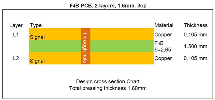
The top and bottom layers consist of 3 oz copper. The F4BM265 dielectric material is situated between these two copper layers, exhibiting a dielectric constant of 2.65.
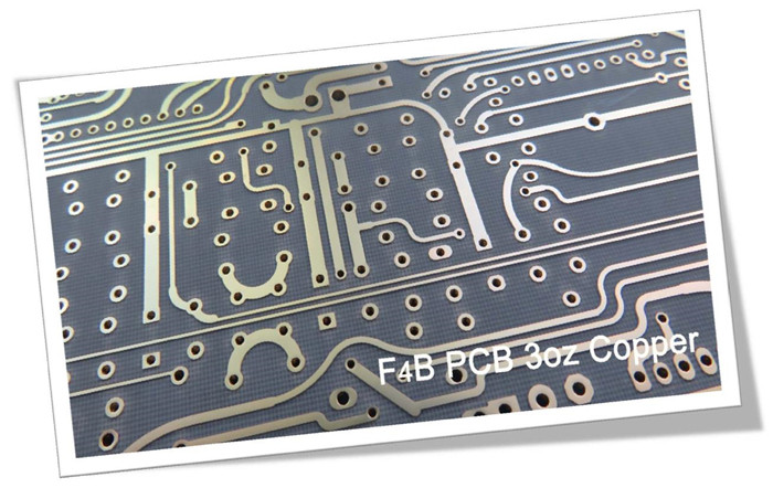
Visual Inspection
In the image of this board, the tracks appear thicker than those on standard boards. The surface finish is immersion gold, with no solder mask or silkscreen present.
PCB Capabilities (F4BM)
PCB Capability (F4BM) |
|||
PCB Material: |
PTFE glass fiber cloth copper clad laminates |
||
Designation (F4BM ) |
F4BM |
DK (10GHz) |
DF (10 GHz) |
F4BM217 |
2.17±0.04 |
0.0010 |
|
F4BM220 |
2.20±0.04 |
0.0010 |
|
F4BM233 |
2.33±0.04 |
0.0011 |
|
F4BM245 |
2.45±0.05 |
0.0012 |
|
F4BM255 |
2.55±0.05 |
0.0013 |
|
F4BM265 |
2.65±0.05 |
0.0013 |
|
F4BM275 |
2.75±0.05 |
0.0015 |
|
F4BM294 |
2.94±0.06 |
0.0016 |
|
F4BM300 |
3.00±0.06 |
0.0017 |
|
Layer count: |
Single Sided, Double Sided PCB, Multilayer PCB, Hybrid PCB |
||
Copper weight: |
0.5oz (17 µm), 1oz (35µm), 2oz (70µm) |
||
Dielectric thickness (or overall thickness) |
0.127mm (dielectric), 0.2mm, 0.25mm, 0.5mm, 0.508mm, 0.762mm, 0.8mm, 1.0mm, 1.5mm, 1.524mm, 1.575mm, 2.0mm, 2.5mm, 3.0mm, 4.0mm, 5.0mm, 6.0mm, 8.0mm, 10.0mm, 12.0mm |
||
PCB size: |
≤400mm X 500mm |
||
Solder mask: |
Green, Black, Blue, Yellow, Red etc. |
||
Surface finish: |
Bare copper, HASL, ENIG, Immersion silver, Immersion tin, OSP, Pure gold, ENEPIG etc.. |
||
The dielectric constant of F4BM material ranges widely from 2.17 to 3.0, while board thickness can vary from 0.13 mm to 12.0 mm. We offer prototype services, small batch production, and mass production service.
Contact Us
If you have any questions, please feel free to contact us.
Thank you for your attention.
Appendix: Data Sheet (F4BM)
Product Technical Parameters |
Product Model & Data Sheet |
|||||||||||
Product Features |
Test Conditions |
Unit |
F4BM217 |
F4BM220 |
F4BM233 |
F4BM245 |
F4BM255 |
F4BM265 |
F4BM275 |
F4BM294 |
F4BM300 |
|
Dielectric Constant (Typical) |
10GHz |
/ |
2.17 |
2.2 |
2.33 |
2.45 |
2.55 |
2.65 |
2.75 |
2.94 |
3.0 |
|
Dielectric Constant Tolerance |
/ |
/ |
±0.04 |
±0.04 |
±0.04 |
±0.05 |
±0.05 |
±0.05 |
±0.05 |
±0.06 |
±0.06 |
|
Loss Tangent (Typical) |
10GHz |
/ |
0.001 |
0.001 |
0.0011 |
0.0012 |
0.0013 |
0.0013 |
0.0015 |
0.0016 |
0.0017 |
|
20GHz |
/ |
0.0014 |
0.0014 |
0.0015 |
0.0017 |
0.0018 |
0.0019 |
0.0021 |
0.0023 |
0.0025 |
||
Dielectric Constant Temperature Coefficient |
-55ºC~150ºC |
PPM/℃ |
-150 |
-142 |
-130 |
-120 |
-110 |
-100 |
-92 |
-85 |
-80 |
|
Peel Strength |
1 OZ F4BM |
N/mm |
>1.8 |
>1.8 |
>1.8 |
>1.8 |
>1.8 |
>1.8 |
>1.8 |
>1.8 |
>1.8 |
|
1 OZ F4BME |
N/mm |
>1.6 |
>1.6 |
>1.6 |
>1.6 |
>1.6 |
>1.6 |
>1.6 |
>1.6 |
>1.6 |
||
Volume Resistivity |
Standard Condition |
MΩ.cm |
≥6×10^6 |
≥6×10^6 |
≥6×10^6 |
≥6×10^6 |
≥6×10^6 |
≥6×10^6 |
≥6×10^6 |
≥6×10^6 |
≥6×10^6 |
|
Surface Resistivity |
Standard Condition |
MΩ |
≥1×10^6 |
≥1×10^6 |
≥1×10^6 |
≥1×10^6 |
≥1×10^6 |
≥1×10^6 |
≥1×10^6 |
≥1×10^6 |
≥1×10^6 |
|
Electrical Strength (Z direction) |
5KW,500V/s |
KV/mm |
>23 |
>23 |
>23 |
>25 |
>25 |
>25 |
>28 |
>30 |
>30 |
|
Breakdown Voltage (XY direction) |
5KW,500V/s |
KV |
>30 |
>30 |
>32 |
>32 |
>34 |
>34 |
>35 |
>36 |
>36 |
|
Coefficientof Thermal Expansion |
XY direction |
-55 º~288ºC |
ppm/ºC |
25, 34 |
25, 34 |
22, 30 |
20, 25 |
16, 21 |
14, 17 |
14, 16 |
12, 15 |
12, 15 |
Z direction |
-55 º~288ºC |
ppm/ºC |
240 |
240 |
205 |
187 |
173 |
142 |
112 |
98 |
95 |
|
Thermal Stress |
260℃, 10s,3 times |
No delamination |
No delamination |
No delamination |
No delamination |
No delamination |
No delamination |
No delamination |
No delamination |
No delamination |
||
Water Absorption |
20±2℃, 24 hours |
% |
≤0.08 |
≤0.08 |
≤0.08 |
≤0.08 |
≤0.08 |
≤0.08 |
≤0.08 |
≤0.08 |
≤0.08 |
|
Density |
Room Temperature |
g/cm3 |
2.17 |
2.18 |
2.20 |
2.22 |
2.25 |
2.25 |
2.28 |
2.29 |
2.29 |
|
Long-Term Operating Temperature |
High-Low Temperature Chamber |
℃ |
-55~+260 |
-55~+260 |
-55~+260 |
-55~+260 |
-55~+260 |
-55~+260 |
-55~+260 |
-55~+260 |
-55~+260 |
|
Thermal Conductivity |
Z direction |
W/(M.K) |
0.24 |
0.24 |
0.28 |
0.30 |
0.33 |
0.36 |
0.38 |
0.41 |
0.42 |
|
PIM |
Only applicable to F4BME |
dBc |
≤-159 |
≤-159 |
≤-159 |
≤-159 |
≤-159 |
≤-159 |
≤-159 |
≤-159 |
≤-159 |
|
Flammability |
/ |
UL-94 |
V-0 |
V-0 |
V-0 |
V-0 |
V-0 |
V-0 |
V-0 |
V-0 |
V-0 |
|
Material Composition |
/ |
/ |
PTFE, Fiberglass Cloth |
|||||||||